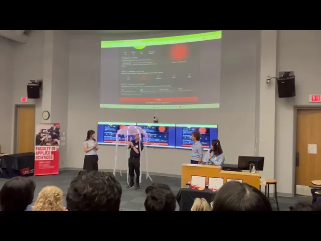

SUMMARY
DURATION
Jan 2026 - Mar 2026
JELLYFISH UMBRELLA
Designed and integrated the electrical system for an interactive Jellyfish Umbrella controlled by an ESP32, featuring addressable LEDs, servo-actuated tentacles, wireless control, and custom PCBs. Placed 3rd in SFU's Faculty of Applied Sciences competition.
ROLE
Member in team of four
PCB Design
LiPo Batteries
Trouble Shooting
ESP32
C++
WiFi
System Integration
Power Electronics
Wiring
Analog Electronics
OVERVIEW
Placed 3rd out of 22 teams in SFU’s annual Faculty of Applied Sciences competition by creating an interactive Jellyfish Umbrella designed to inspire K–12 students to explore STEM. Our team wanted to create something both hands-on and visually engaging, combining a clear umbrella, LED strips, 3D-printed tentacles with a pulley system, and various fabrics to bring the concept to life.


The umbrella was controlled by an ESP32, enabling wireless control through a web application. Users could actuate the 3D-printed tentacles via a two-servo pulley mechanism and customize the LED strip colours and lighting patterns in real time.
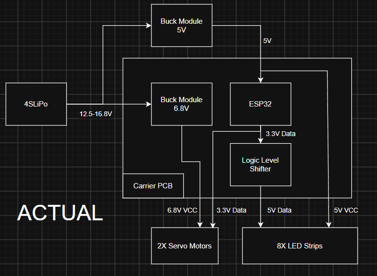
The system was initially powered by a 2S LiPo battery before being upgraded to a 4S LiPo. Power was monitored using a custom battery monitoring PCB that I designed, stepped down through a buck converter, and distributed via a custom ESP32 carrier board that I also designed featuring bypass and bulk capacitors, a logic-level shifter, and modular connectors for the LED strips and servo motors.


1.1 CONTRIBUTION
Designed and built a battery-monitoring PCB to shut off power when the battery voltage was too low.
Designed and built a carrier board for power distribution, ESP32 integration, buck converter integration, and mounting the battery-monitoring PCB.
Cut, wired, and crimped all LED strips for system integration.
Configured and wired two buck converters for system integration.
Programmed LED patterns and colour changes in C++, and contributed to servo-control and Wi-Fi functionality.
CONSTRAINTS / REQUIREMENTS
Creating an interesting and interactive project that would appeal to K-12 students
Making the project in under 2 months
Working with a system under battery power
Integrating LED lights, motors and a microcontroller
DESIGN
3.1 SYSTEM OVERVIEW
The electrical system consisted of a 2S LiPo battery, a custom battery monitor PCB, a buck converter module off Amazon and a custom carrier board PCB for an ESP32, logic level shifter for LED strips, and connectors for the LED strips and servo motors.
This was the planned system but we had to change it later because battery monitor board had issues requiring a workaround and we had to use a separate buck module for servos since they need more voltage than 5V.

2S LiPo battery for powering system: here
PCB Monitor Board for monitoring battery power
Carrier Board for housing electrical system components for a compact package
Buck Converter Module for 6.8V for powering servo motors: here
Buck Converter Module for 5V for powering LED strips and ESP32: here
ESP32 for controlling LEDs, motors and receiving commands from a webapp
LED Strips for visually appealing jellyfish like look: here
Miuzei Servos for pulling tentacles in and out with pulley system: here
3.2 COMPONENTS
1.


2.
2.
3.


3.
4.
5.


6.
8.
3.3 BATTERY MONITOR BOARD
3.3.1 SCHEMATIC
The purpose of battery monitor board was to use comparators to monitor the voltage level of the LiPo and indicate the voltage level via an RGB LED and a buzzer, as well as shut off power to the system via high-side switching with a PMOS.

Schematic details
A through-hole XT60 connector connects the LiPo battery to the board, with an additional screw terminal provided as a backup connection option.
An XT60 was selected because it is commonly used on LiPo batteries.
A 5V linear regulator powers the comparators, voltage reference, buzzer, and RGB LED.
The regulator and all downstream electronics are protected against reverse polarity using a Schottky diode rated to withstand the battery voltage and the regulator's maximum current draw.
The buzzer is low-side switched by U2A when the battery voltage falls below 6.5V to warn the user.
An SPDT switch allows the buzzer to be manually disabled if needed.
The RGB LED indicates battery voltage:
Green: >7.0V
Orange: 6.5–7.0V
Red: <6.5V
Two comparators monitor the LiPo voltage and control the RGB LED and buzzer. More importantly, they control a PMOS that disconnects the battery from the buck converter when the voltage falls below 6.5V.
Zener diodes on the inverting inputs clamp the monitored voltage, with bypass capacitors providing filtering.
Hysteresis is implemented through positive feedback using 93.1k resistors. The intended switching thresholds were 6.5V for U2A and 7.0V for U2B, with separate higher thresholds to prevent rapid output switching as the battery voltage slowly decreases.
However, I realized hysteresis implementation was incorrect during testing because the comparator output is pulled up to the battery voltage rather than the 5V reference. This behavior was intentional for another aspect of the circuit, but resulted in an incorrect hysteresis.
The PMOS output is connected to screw terminal J2, which supplies the protected battery voltage to the buck converter module.
3.3.2 PCB

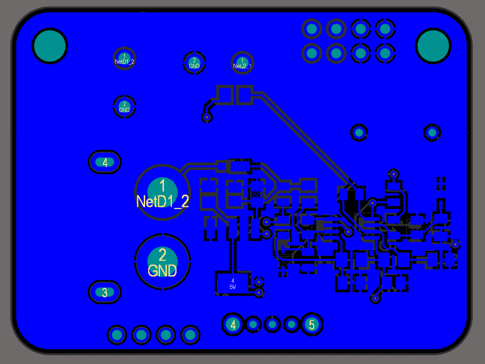

PCB details
2 layer board
Components populate both layers
Larger copper pours are used for battery current path
Junction pins on bottom of board are used to mount battery monitor to carrier board along with an earlier idea to provide power through the pins to the carrier, but I didn't end up going with it


3.3.3 TESTING / PROBLEMS

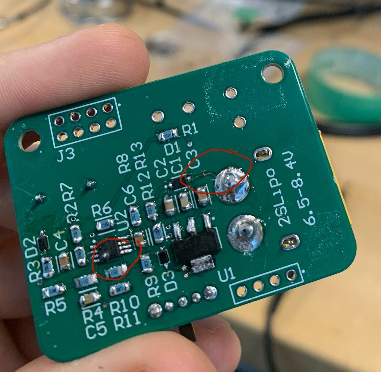

Testing
After assembling the board and beginning testing, the comparator internally shorted after a few minutes, as shown in the middle image and the left red circle. Shortly afterward, the trace connecting the XT60 connector to the Schottky diode also burned out, shown by the right red circle, likely due to the high current caused by the short.
Main issue
The main issue identified with this board was the implementation of the comparator hysteresis.
The comparator has an open-collector output that is pulled up to the battery voltage. This was intentionally done so that when the comparator output is LOW, the PMOS receives a sufficiently large Vsg to turn it fully off and disconnect the battery. If the output were instead pulled up to the 5V reference, the PMOS may not turn off completely because the resulting Vsg could be insufficient.
However, pulling the comparator output up to the battery voltage changes the voltage at the hysteresis feedback network. As a result, the feedback resistor cannot simply be treated as being in parallel with R4 and R5 when ON and OFF in the reference divider, since the comparator output voltage is not fixed at either 0V or 5V.
This causes the feedback voltage and reference voltage to vary with the battery voltage, resulting in unintended current paths that can back-feed the 5V regulator and other components.
I suspect this was the primary design issue. However, it does not necessarily explain why the comparator itself failed. During testing, the battery voltage should have been above the U2A switching threshold, meaning the comparator should not have been in the problematic switching region. Therefore, an assembly or component-level issue may also have contributed to the comparator failure.
What I should have done was initially power the circuit using a DC supply and limiting the output current to prevent board/component damage from a potential short circuit from an assembly error or design issue. This would have allowed me to identify, diagnose and resolve any problems before connecting the PCB directly to the battery. Once the circuit could be validated with the DC supply, I then could have safely proceeded to battery-powered testing.
3.3.4 IMPROVEMENTS & LESSONS LEARNED
Things to improve for next board iteration
Use a 5V pull-up for the comparator output to maintain a consistent hysteresis reference, and then use a buffer or NMOS in low-side configuration to level shift the comparator output to the battery voltage for proper PMOS switching. Alternatively, eliminate hysteresis and continue pulling the comparator output up to the battery voltage.
Add reverse-polarity protection for the battery using a PMOS. The current design protects the control electronics through the Schottky diode; however, with the battery connected in reverse, current can flow through the PMOS body diode and create a short circuit.
Increase the trace width of Schottky and regulator connection
Conclusion
Due to competition timelines and the board not being critical to the final system, a second PCB revision was not completed. Despite this, I gained experience interfacing with LiPo batteries, implementing hysteresis, driving buzzers and RGB LEDs, and using P-channel MOSFETs for switching.
3.4 CARRIER BOARD

3.4.1 SCHEMATIC
The purpose of the carrier board is to provide a compact package for interfacing with all the system electronics. The board houses the ESP32, provides power distribution, includes a logic-level shifter for the LED data lines, provides headers for the LED strips, and includes junction pins for connecting the servos.

Schematic details
Screw terminal J12 supplies 5V from the buck converter.
The 5V supply passes through multiple bypass capacitors to filter noise from the buck converter.
Header pins J9 and J10 connect the ESP32 pins to the board.
The ESP32's 3.3V data signals pass through U1, a logic-level shifter, which converts them to 5V for controlling the LED strips.
A 330R series resistor is placed on the 5V data lines to reduce potential signal ringing caused by the long LED-strip connections.
A 220uF bulk capacitor provides additional current during sudden load transients.
Bypass capacitors are placed approximately every two LED strips to help filter high-frequency noise.
Junction pins J11 connect the servo motors to the board and include additional bypass capacitors for filtering.
3.4.2 PCB


PCB details
2 layer board
Components populate both layers
Larger copper pours are used for servo and LED strips power
Area is cleared for mounting of the battery monitor on the bottom and the buck converter module on the top with some stand-offs

3.4.3 TESTING
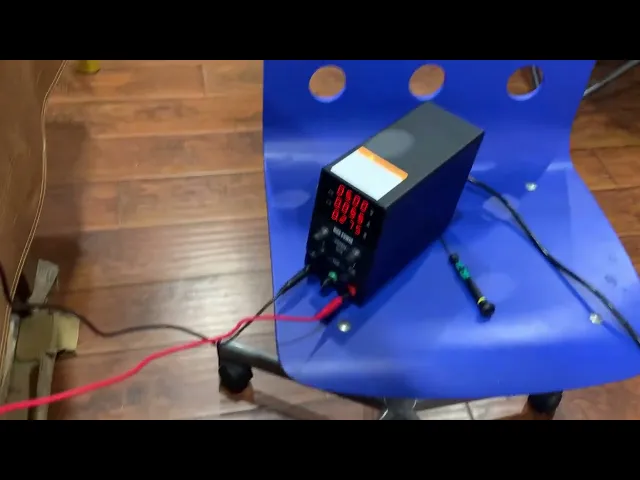
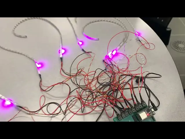
Tested first with 1 LED strip and power supply. Board worked.
Than tested with all LED strips and supply and also worked.
3.4.4 CONCLUSION
The carrier board successfully provided a compact and modular package for the system electronics, simplifying the integration of the ESP32, LED strips, and servo motors within the umbrella.
SYSTEM INTEGRATION
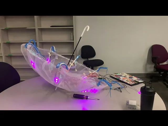
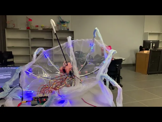
With the PCBs tested and my teammate's mechanical pulley system successfully tested, we moved on to assembling the complete system.
Problems Encountered
The motors were being torqued quite a bit and the 5V wasn't enough for all the tentacles to curl in.
Solution: We had to get an extra buck converter as mentioned before. This extra buck converter was a fixed 5V output so we used the original buck converter to supply 6.8V to the servos and 5V for the ESP32 and LED strips.
The 6.8V buck converter couldn't supply enough power to the servos with the max 8.4V of 2S LiPo. We tested and found it need minimum 11V.
Solution: A friend came in clutch and got us a 4S LiPo giving us a max 16.8V, allowing us to power the servos sufficiently

RESULTS
Despite the challenges we encountered throughout the project, we managed to pull through with some late nights and deliver a project that the entire team was proud of. Our hard work paid off, earning us 3rd place out of 22 teams in the competition.